
Infrared inspection to predict fire risks
In previous chapters we’ve seen that fire is a significant hazard for businesses, that electrical problems are the source of many fires and that poor connections, often hidden within switchgear, distribution panels, transformers and other equipment, are among the most frequent types of electrical problem that can lead to fire. Fortunately, technology is available that allows faulty electrical connections to be detected early, so that the issue can be corrected before it results in fire. This technology is thermography.
Thermal cameras reveal defects invisible to the naked eye
Any object that is warmer than absolute zero (about -273 ºC) emits infrared radiation. Our eyes can’t see this, but a thermal camera can and can also convert it into a visible image with colours that relate to temperature. Most thermal cameras can also provide temperature measurements of specific points in the image.
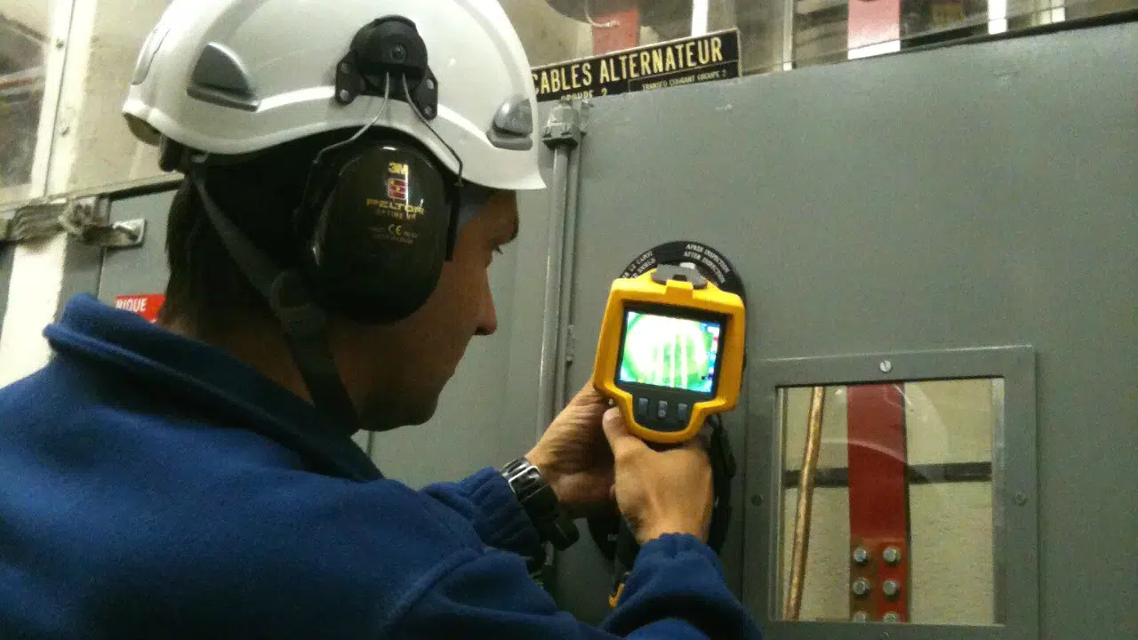
In simple terms, this means that if a thermal camera is pointed at an item of electrical equipment, hotspots can be instantly seen on the screen. Further, non-contact measurement of the temperature of the hotspots can be easily performed. In this way, poor connections and other sources of unwanted heating in electrical equipment can be quickly and positively located. Faults can, therefore, be rectified before they lead to fires.

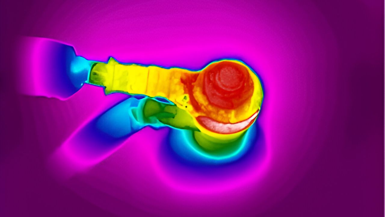
These images show an example of thermography in use. The thermal camera has been pointed at the top connection of a fuse, which is of the type where the fuse itself has a blade-shaped connection that is inserted between two sprung retainers in the fuse holder. The picture on the left is a normal visible-light photograph (most thermal cameras offer the facility for capturing visible light photographs) and shows the general arrangement.
The picture in the centre is a thermographic image and uses colours to show the temperatures of the components in the image. A temperature key is provided on the right of the image, and it can be clearly seen that the top connection of the fuse – and the top of the fuse itself – is considerably hotter than the other components. In the picture on the right, the thermograph has been used to capture two temperature measurements: that of the top of the fuse, which is shown as 37.9 ºC, and that of the surrounds, which is shown as 9.1 ºC.
The conclusion is that the temperature of the top of the fuse is almost 30 ºC above ambient. This is not hot enough to cause a fire, but it certainly indicates that the fuse, the fuse holder, and the connections need to be examined before further deterioration – and further heating – occur.
NFPA 70B Recommendations for Electrical Equipment Maintenance
It’s not hard to see that thermographic inspection has a lot to recommend it as a tool for aiding the effective maintenance of electrical equipment. In fact, National Fire Protection Agency (NFPA) 70B: Recommended Practice for Electrical Equipment Maintenance, states that thermography should play a key role in monitoring faults in energised electrical equipment. It recommends that transformers, switchgear and distribution equipment should be inspected at least once a year and, in some cases, quarterly. It also states that these inspections should be carried out with the connections and conductors exposed, and with the equipment under full load.
Risks and inconveniences of thermography on electrical equipment
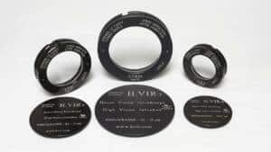
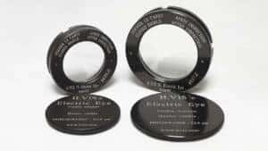
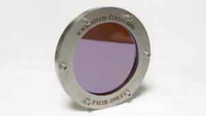
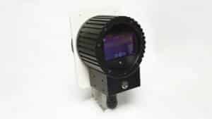
The last sentence of the NFPA recommendations in particular creates a problem. Infrared cameras cannot see through enclosure doors. This applies even to doors that have Plexiglas inspection windows because Plexiglas, while transparent to visible light, blocks infrared radiation. In other words, for an infrared inspection to be carried out, it seems that enclosure doors must be opened. This has two consequences: as we have seen in earlier chapters, the equipment must be deenergised for the doors to be opened safely and, since no current will then be flowing, the hotspots will cool quickly making it hard to detect them reliably. There has to be a better way and there is! In fact, there are two! Infrared windows are visualization interfaces, composed of an optomecanic structure that is fixed on the façade of the plastrons of the electrical equipment. These infrared windows enable to control operating equipment, while protecting the thermograph.
Wintech Groupe invites you to continue your reasearch on the reduction of industrial fire risks by reading our other articles on infrared technology.

In previous chapters we’ve seen that fire is a significant hazard for businesses, that electrical problems are the source of many fires and that poor connections, often hidden within switchgear, distribution panels, transformers and other equipment, are among the most frequent types of electrical problem that can lead to fire. Fortunately, technology is available that allows faulty electrical connections to be detected early, so that the issue can be corrected before it results in fire. This technology is thermography.
Thermal cameras reveal defects invisible to the naked eye
Any object that is warmer than absolute zero (about -273 ºC) emits infrared radiation. Our eyes can’t see this, but a thermal camera can and can also convert it into a visible image with colours that relate to temperature. Most thermal cameras can also provide temperature measurements of specific points in the image.
In simple terms, this means that if a thermal camera is pointed at an item of electrical equipment, hotspots can be instantly seen on the screen. Further, non-contact measurement of the temperature of the hotspots can be easily performed. In this way, poor connections and other sources of unwanted heating in electrical equipment can be quickly and positively located. Faults can, therefore, be rectified before they lead to fires.
These images show an example of thermography in use. The thermal camera has been pointed at the top connection of a fuse, which is of the type where the fuse itself has a blade-shaped connection that is inserted between two sprung retainers in the fuse holder. The picture on the left is a normal visible-light photograph (most thermal cameras offer the facility for capturing visible light photographs) and shows the general arrangement.
The picture in the centre is a thermographic image and uses colours to show the temperatures of the components in the image. A temperature key is provided on the right of the image, and it can be clearly seen that the top connection of the fuse – and the top of the fuse itself – is considerably hotter than the other components. In the picture on the right, the thermograph has been used to capture two temperature measurements: that of the top of the fuse, which is shown as 37.9 ºC, and that of the surrounds, which is shown as 9.1 ºC.
The conclusion is that the temperature of the top of the fuse is almost 30 ºC above ambient. This is not hot enough to cause a fire, but it certainly indicates that the fuse, the fuse holder, and the connections need to be examined before further deterioration – and further heating – occur.
NFPA 70B Recommendations for Electrical Equipment Maintenance
It’s not hard to see that thermographic inspection has a lot to recommend it as a tool for aiding the effective maintenance of electrical equipment. In fact, National Fire Protection Agency (NFPA) 70B: Recommended Practice for Electrical Equipment Maintenance, states that thermography should play a key role in monitoring faults in energised electrical equipment. It recommends that transformers, switchgear and distribution equipment should be inspected at least once a year and, in some cases, quarterly. It also states that these inspections should be carried out with the connections and conductors exposed, and with the equipment under full load.
Risks and inconveniences of thermography on electrical equipment
The last sentence of the NFPA recommendations in particular creates a problem. Infrared cameras cannot see through enclosure doors. This applies even to doors that have Plexiglas inspection windows because Plexiglas, while transparent to visible light, blocks infrared radiation. In other words, for an infrared inspection to be carried out, it seems that enclosure doors must be opened. This has two consequences: as we have seen in earlier chapters, the equipment must be deenergised for the doors to be opened safely and, since no current will then be flowing, the hotspots will cool quickly making it hard to detect them reliably. There has to be a better way and there is! In fact, there are two! Infrared windows are visualization interfaces, composed of an optomecanic structure that is fixed on the façade of the plastrons of the electrical equipment. These infrared windows enable to control operating equipment, while protecting the thermograph.
Wintech Groupe invites you to continue your reasearch on the reduction of industrial fire risks by reading our other articles on infrared technology.